Export
Contents
エクスポート
データの取得/アライメント/変換は、他のソフトウェアにそのデータを送ることができて、初めて意味を持ちます。エクスポート機能を使って、他のソフトウェアでインポートできるファイルを作成することができます。
このスキャニングソフトウェアには、2つのタイプのエクスポート(手動および自動)があります。手動エクスポートは、いつでも、どのような種類のプロジェクトでも利用できます。自動エクスポートはプロジェクトに特化しています。 自動エクスポート機能は、オプションダイアログ画面で設定できます。
フォーマット
このスキャニングソフトウェアでは、以下のフォーマットがサポートされています:
- 取得
- 'Scan' : このエクスポート機能は、スキャナーで取得されたそれぞれの3D画像のファイル (.cri) と、データの詳細が含まれる追加のファイル (.scan)を作成します。このスキャニングソフトウェアのみで使用するデータで、すべてのファイルを一緒に保管する必要があります。
- 'ZScan' : このエクスポート機能は、Scanエクスポート機能と同じ情報を保存しますが、すべてを1つのファイルに圧縮します。
- メッシュ
- 'STL ASCII/Binary' : STLファイルフォーマットは最もよく使われる形式です。ほとんどの3DソフトウェアはSTLファイルに対応しています。3Dオブジェクトのすべての情報を保存しない(例:色や、各面間のコネクションなど)ため、異なるソフトウェアが同じSTLファイルを読んだ場合に、異なる結果が表示されることがあります。
- 'OFF ASCII' : OFFフォーマットは非常にシンプルなファイル形式で、こちら[OFF Format]より内容を確認できます。この形式はSTLフォーマットよりも多くの情報を保存します。
- 'PLY ASCII/Binary' : PLYフォーマットは、OFFフォーマットと同じように、3Dデータに関するより多くの情報を含みますが、他のソフトウェアではあまりサポートされていません。
- 'OBJ' : OBJフォーマットはASCIIのみで、3Dデータに関して最も多くの情報を含みます。これには、色の情報も含まれ、ほとんどのソフトウェアでサポートされています。
最も高い互換性が必要な場合は、STLが最適となります。目的が最も正確な3Dデータを保存することであれば、OBJフォーマットがより好ましい形式となります。
手動エクスポート
取得データとメッシュをディスクに保存するには、2つの方法があります。
シングルオブジェクトエクスポート
プロジェクトから1つの部品をエクスポートするには:
- プロジェクトツリーの部品を右クリックします
- コンテクストメニューから、Export..を選択します。
- ポップアップ表示されるダイアログ画面から、ファイルを保存する場所、ファイル名、データフォーマットを選択します。
マルチオブジェクトエクスポート
同じファイルにプロジェクトから1つ以上の部品をエクスポートするには:
- プロジェクトツリーから同時にエクスポートするすべてのデータを選択します
- ファイルメニューから、Export Visible(表示部分をエクスポート)機能選択します
- ポップアップ表示されるダイアログ画面から、ファイルを保存する場所、ファイル名、データフォーマットを選択します。
自動エクスポート
自動エクスポート機能を使用するには、メインツールバーのExport To CAD(CADへエクスポート)ボタンをクリックします。その後、ソフトウェアは選択されたExporter Profile(エクスポータープロファイル)に従って、すべてのプロジェクトデータをエクスポートします。
エクスポータープロファイル
エクスポータープロファイルはパラメーターのセットで、特定のCADシステムに対してどのようにデータをエクスポートするかソフトウェアに指示します。
エクスポータープロファイルは、オプションパネルから変更、追加、名前の変更を行うことができます。
「default」という1つのプロファイルのみがある場合、Export To CADボタンをクリックすると、これが自動的に使用されます。
1つ以上のプロファイルがある場合、ポップアップでどのプロファイルを使用するか選択できます。
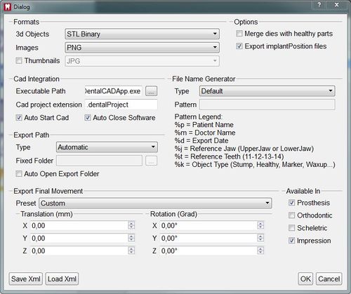
![]() を押すと、エクスポートダイアログが開くので、その特定のエクスポートのみに対するエクスポートプロファイルを変更することができます。
を押すと、エクスポートダイアログが開くので、その特定のエクスポートのみに対するエクスポートプロファイルを変更することができます。
フォーマット
ソフトウェアは取得データの3D形状と、2D画像をエクスポートして、咬合をドキュメント化し、各3Dオブジェクトのサムネイルをエクスポートすることもできます。
このセクションでは、どのフォーマットを使用するか選択できます。
使用しているCADシステムで、どのフォーマットが適しているか確認して下さい。
オプション
- Merge dies with healthy parts
- If this option is enabled the software will merge all the dies and the healthy parts and export only one file for the entire jaw; if it's disabled the software will export one file for every die and one file for the healthy parts of the jaw
- Export implantPosition files
- If this option is enabled the software will export a special "implantPosition" file with the information about the alignment of an implant marker that can be imported by Exocad.
Cad Integration
- Executable Path
- Select here the path to the Cad software to automatically launch it after exporting the data
- Cad project extension
- Input the extension of the Cad project so the software can invoke the cad with the right project file
- Auto Start Cad
- Check this box to start the Cad automatically after exporting the data
- Auto Close Software
- Check this box to automatically close the scan software after exporting the data
Export Path
This section allows to choose where the exported files will be saved. There are 3 different path selections
- Automatic
- The software will choose automatically the export folder. If a Cad project extension was selected, the file will be exported in the folder in which the cad project is stored, if available. If no cad project extension was selected, the file will be exported in the scan project folder
- Ask
- The software will ask to define the export folder for every project
- Fixed Folder
- The software will export to the same folder every time.
By checking "Auto Open Export Folder", the software will automatically open the export folder after exporting the data
File Name Generator
This section allows to choose how the software will name the exported files. There are 2 different generators
- Default
- This generator will use the "Exocad" name format "projec name-reference jaw-item name-teeth.extension"
- User Pattern
- This generator allows to use special tags to create file names. Each tag represents a different item.
An example of a user pattern is "%m/%p/%d/%j-%k-%t"
In a project with 2 stump on the lower jaw and an antagonist the exporter will:
- Create a folder with the name of the doctor
- Create a sub-folder with the name of the patient
- Create a sub-folder with the date
- Save the stumps as lowerjaw-stump-36.stl and lowerjaw-stump-35.stl
- Save the healthy parts as lowerjaw-healthy.stl
- Save the antagonist as upperjaw.stl
Available In
Each export profile can work in one or more different kinds of project.
The checkboxes allow to choose in which project this profile can be used.
Export Final Translation
In each system, a spacial reference for positioning of the objects is defined. Our system uses this reference:
- XY Plane as the Occlusion Plane.
- YZ plane as the Symmetric Plane.
Exocad uses this same reference system.
Many orthodontic software use the following reference:
- XZ Plane as the Occlusion Plane
- XY Plane as the Symmetric Plane
Here it is possible to select the reference system used by the CAD system in use, to shift the objects' positions in a correct view.


