Difference between revisions of "Man ImplantAlign/fr"
L.leonardi (talk | contribs) (Created page with "= Acquisition des Marqueurs =") |
L.leonardi (talk | contribs) (Created page with "Dans les projets sur implants n’est pas possible d’acquérir directement l’information de la connexion implantaire parce qu'elle est trop petite et en métal et elle n...") |
||
| Line 3: | Line 3: | ||
= Acquisition des Marqueurs = | = Acquisition des Marqueurs = | ||
| − | + | Dans les projets sur implants n’est pas possible d’acquérir directement l’information de la connexion implantaire parce qu'elle est trop petite et en métal et elle n’est pas donc visible comme un moignon ou comme un modèle en plâtre. | |
Moreover, the fitting has to be mechanically perfect, with no margin of error. | Moreover, the fitting has to be mechanically perfect, with no margin of error. | ||
Revision as of 12:39, 2 February 2016
Acquisition des Marqueurs
Dans les projets sur implants n’est pas possible d’acquérir directement l’information de la connexion implantaire parce qu'elle est trop petite et en métal et elle n’est pas donc visible comme un moignon ou comme un modèle en plâtre.
Moreover, the fitting has to be mechanically perfect, with no margin of error.
To solve this problem, the implant connection is not directly scanned but an Implant Marker or Scan Body is used in its stead. A Scan Body is a specific object, designed to be scanned, which fits exactly over the implant.
The scan of the implant marker itself is not enough: its resulting data will be used to compute the exact position of the implant interface. In order to carry out this operation, an Implant Library is needed .
The alignment to the implant library can be performed in the CAD software. However, using an implant library for Exocad's Platform, the user can perform this operation directly in the scanning software OpticalRevEng Dental, in order to get better results.
Implant Selection
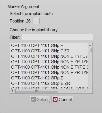
After the mesh generation, by selecting the mesh of an implant marker from the project tree, the Marker Alignment button will appear in the Main Toolbar. Click on this button to open the Implant Selection dialog.
In this Dialog there are:
- A tooth position selection (the button with three dots ...) that can be used only in Free Mode to select the tooth position of an implant
- An implant list with all the implants available in the current Implant Library
- A Filter box where it is possible to write part of the name of the needed implant. All the implants that match the name will be showed in the implant list
Select the implant to be used and click the Select Button.
Attention while choosing the right implant from the library. Many implant libraries have different versions of every implant connection. For example:
- Engaging Connections : the connection can not rotate on the implant, suggested for abutments or single restorations
- Not-Engaging Connections : the connection can rotate on the implant, suggested for bars and bridges
- For Zirconia : connections with specific shapes, suited for zirconia restorations
If the wrong implant is selected, it is possible to repeat the procedure to replace the old aligned connection with a new one.
If the CAD design is launched using a wrong connection it will be necessary to restart all the design from the beginning
Marker Alignment
When selecting the implant connection, the software will start the Manual Alignment mode.
The acquired marker mesh will need to be aligned to the library marker shape. From this data the connection position will be computed.
This procedure has to be performed for every marker of the project. The CAD Export will issue a warning if one or more marker alignments are missing.


