Alignment
Contents
Ausrichtung
Wenn mehrere Objekte gescannt werden, wird ihre relative Position am Anfang nicht aufgenommen. Um an den erfassten Daten korrekt zu arbeiten, muss diese in einem Bezugssystem aufgenommen werden.
Der Nutzer muss vor allem das Bild auswählen, das als Bezug für weitere Scanbilder gilt. Bei Strukturprojekten identifiziert die Software das Bezugselement jedes Elements automatisch.
Jedes Mal, wenn eine neue Information erfasst wird, ist es notwendig, neue Daten am Bezugsbild oder einem anderen, am Rest des Projekts schon ausgerichteten Scanbild, auszurichten.
Jedes gescannte Element hat ein bestimmtes Bezugsbild. Der Projektbaum zeigt diese Abhängigkeitsbeziehung: Jedes Tochterelement wird am entsprechenden Mutterelement ausgerichtet.
Automatische Ausrichtung
OpticalRevEng Dental kann Bilder automatisch ausrichten:
- Im Projektbaum das Element auswählen, das am Projekt auszurichten ist.
- Auf das Ausrichtungsicon in der Hauptwerkzeugleiste klicken.
Die Software identifiziert so das Bezugselement, analysiert das auszurichtende Scanbild mit dem jeweiligen Bezugselement und verschiebt das erste Element, um es an die Position des zweiten anzupassen.
Sollte es für die Software unmöglich sein, eine Ausrichtungsposition zu finden, wird die Funktion manuelle Ausrichtung gestartet.
´
Manuelle Ausrichtung
Die manuelle Ausrichtung wird jedes Mal gestartet, wenn die Software keine automatische Ausrichtung ausführen kann. Es ist außerdem möglich, diese Funktion durch längeres Drücken auf ![]() in der Hauptwerkzeugleiste zu aktivieren.
in der Hauptwerkzeugleiste zu aktivieren.
Interface
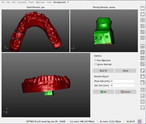
Das Bild zeigt das Interface der manuellen Ausrichtung:
Das Interface besteht aus vier Teilen:
- Im Fenster oben links wird das Bezugselement der Projektdatei angezeigt
- Im Fenster oben rechts wird das bewegliche Objekt angezeigt, der seine ursprüngliche Position verlässt, um sich an das Bezugssystem der Projektdatei anzupassen
- Im unteren mittleren Fensterteil werden beide Objekte angezeigt, damit der Nutzer die Position des beweglichen Objekts in Bezug auf das Bezugselement sehen kann.
- Im Fenster unten rechts sind einige Optionen sowie ein Zahlenbericht verfügbar.
Procedure
To manually align the elements:
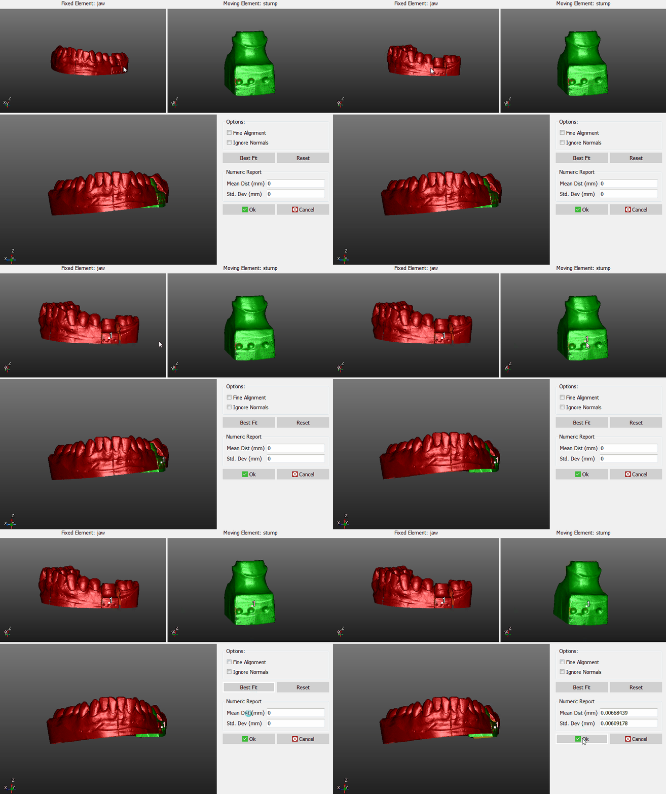
- Place both the reference object and the moving object in the same point of view, until the parts in common are visible
- Click on the same point on both the objects
- Check in the 3D view below, if the position is more or less correct (it's not necessary, at this stage, to find the perfect position)
- Click the Best Fit button on the right
If the two objects have enough points in common, the software will find the best alignment between them. Visually check the alignment on the bottom 3D View or by reading the values in the Numeric Report.
If the alignment is correct, click Ok to confirm the new position of the moving object.
Otherwise, click the Reset button and restart the alignment.
Options
There are two options available during the manual aligment:
- Fine Alignment : usually Best Fit moves the object up to 1mm closer to the reference. If the parts in common between the two objects are really small ,use Fine Aligment to move the object not more than 0.1mm closer to the reference
- Ignore Normals : allows the user to align the internal part of an object to the external part of another, and viceversa.


