Alignment
Contents
Соотношение
Когда сканируются одновременно несколько объектов, их положение относительно друг друга не фиксируется. Для корректной работы с данными сканирования, все изображения считываются по одной опорной системе.
Во-первых, пользователю нужно определить, какое изображение будет использовано как опорное. В Структурированных проектах программа автоматически запускает эту процедуру.
Каждый раз при получении новой информации её необходимо "совместить" с другими данными Опорного изображения или с Другим изображением, сопряженным с проектом
Каждая получаемая информация будет иметь определенное Опорное изображение. Дерево проекта фиксирует отношения между ними, так каждый дочерний элемент будет отнесен к своему родственному звену.
Прямое соотнесение
OpticalRevEng Dental может автоматически соотносить изображения:
- Выбрать в дереве проекта элемент, который должен быть соотнесен к остальным элементам в проекте.
- Нажать на кнопкуСоотношение в Панели инструментов
Программа выберет опорный элемент, проанализирует выделенное опорное изображение и определит корректное положение выделенного элемента по отношению к опорному. Если никакого соотнесение не было определено системой, будет запущено Ручное соотнесение
Manual Alignment
The manual alignment starts every time the software can not perform a Direct Alignment. The user can also acceed this tool by holding ![]() when clicking the Alignment Button in the Main Toolbar
when clicking the Alignment Button in the Main Toolbar
Interface
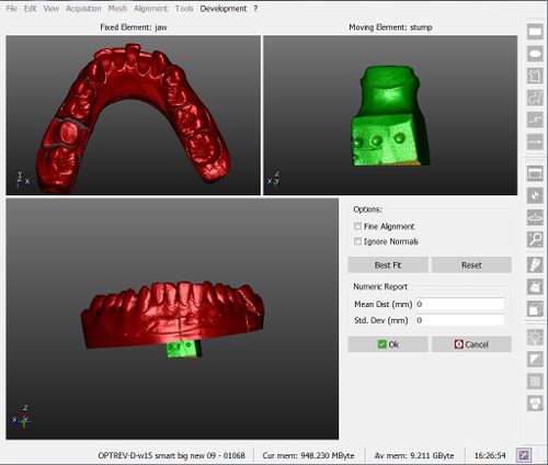
The picture here below shows the interface of the manual alignment:
There are 4 different areas in this screen:
- On the top left is displayed the reference object, which gives the reference position for all the project data
- On the top right is shown the moving object, that has to be moved from its current position and placed in the same reference system of all the other project data
- On the bottom are displayed both objects, so that the user can check the current position of the moving object
- On the bottom right some options and a Numeric Report are available
Procedure
To manually align the elements:
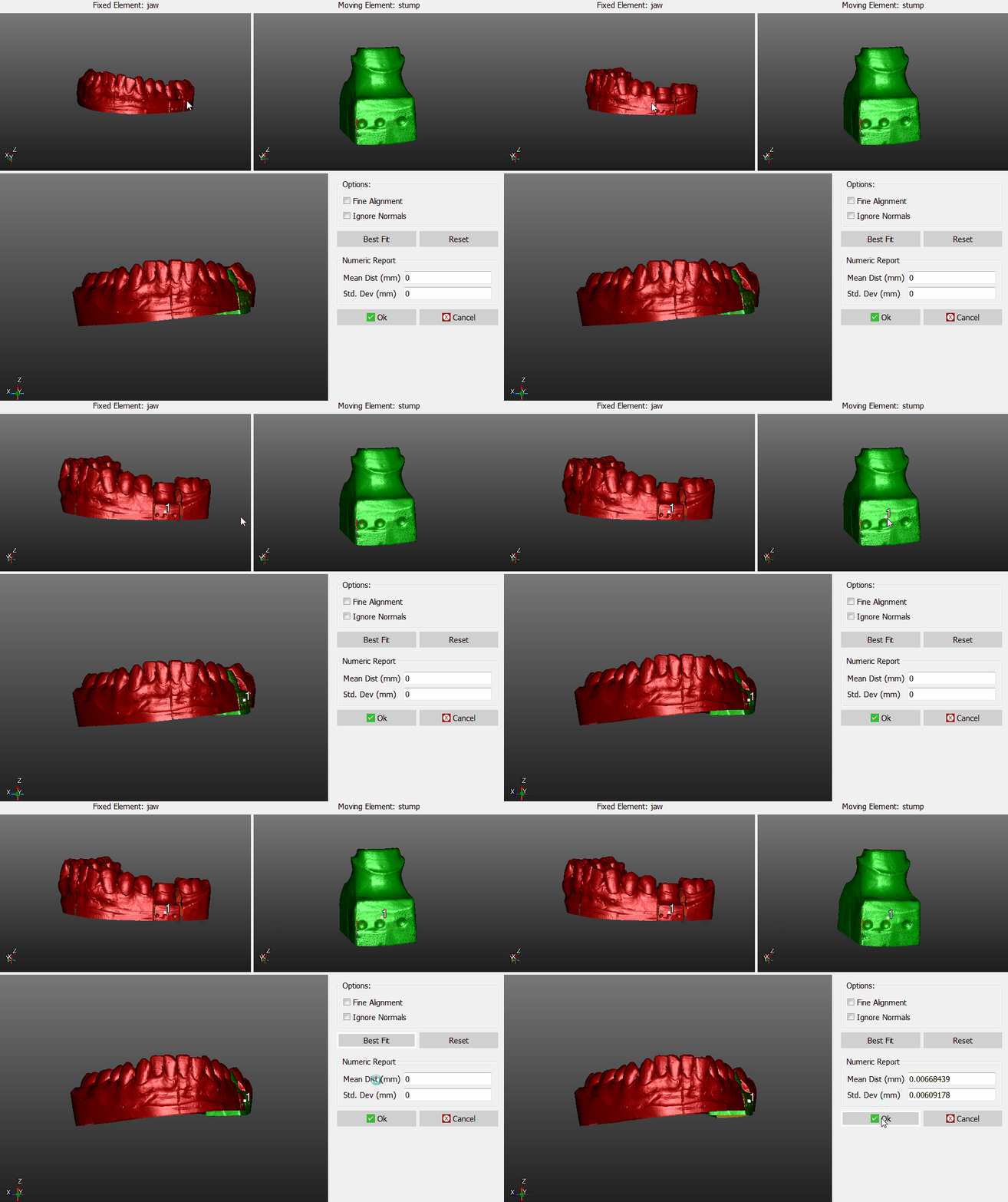
- Place both the reference object and the moving object in the same point of view, until the parts in common are visible
- Click on the same point on both the objects
- Check in the 3D view below, if the position is more or less correct (it's not necessary, at this stage, to find the perfect position)
- Click the Best Fit button on the right
If the two objects have enough points in common, the software will find the best alignment between them. Visually check the alignment on the bottom 3D View or by reading the values in the Numeric Report.
If the alignment is correct, click Ok to confirm the new position of the moving object.
Otherwise, click the Reset button and restart the alignment.
Options
There are two options available during the manual aligment:
- Fine Alignment : usually Best Fit moves the object up to 1mm closer to the reference. If the parts in common between the two objects are really small ,use Fine Aligment to move the object not more than 0.1mm closer to the reference
- Ignore Normals : allows the user to align the internal part of an object to the external part of another, and viceversa.


