Difference between revisions of "Man Align/fr"
L.leonardi (talk | contribs) (Created page with "L’alignement manuel est démarré chuque fois que le logiciel ne peut pas compléter un '''Alignement Direct'''. Il est aussi possible d’accéder à cette fonction en appu...") |
L.leonardi (talk | contribs) (Created page with "L’image ci-dessous montre l’interface de l’alignement manuel") |
||
| Line 27: | Line 27: | ||
== Interface == | == Interface == | ||
| − | + | L’image ci-dessous montre l’interface de l’alignement manuel | |
{{Screenshot|Dental_2_5_manualAlignment.jpg}} | {{Screenshot|Dental_2_5_manualAlignment.jpg}} | ||
Revision as of 16:19, 1 February 2016
Contents
Alignement
Lorsqu’on numérise plusieurs d’objets, leur position n’est pas enregistrée. Pour travailler correctement avec les données acquises il faut les adapter à un système de référence.
L’utilisateur doit identifier quelle acquisition est utilisée comme référence pour toutes les autres. Dans les Projets Structurés, le logiciel identifie automatiquement la référence de chaque élément
Chaque fois qu’une information nouvelle est acquise il faut aligner la donnée nouvelle à l’Acquisition de Référence ou à une acquisition déjà alignée au reste du projet
Chaque élément acquis a une Acquisition de Référence spécifique. L’Arbre du Projet montre la relation de dépendance : chaque élément enfant est aligné à son élément parent
Alignement Direct
OpticalRevEng Dental peut aligner les Acquisitions automatiquement
- Sélectionner dans l’Arbre du Projet l’élément à aligner au reste du projet
- Cliquer sur l’icône Alignement dans la Barre d’Outils Principale
The software will choose the reference, it will analyze the selected acquisition and the reference and it will identify the correct position of the selected item with respect to the reference.
If no alignment can be identified by the software, a Manual Alignment will start.
Alignement Manuel
L’alignement manuel est démarré chuque fois que le logiciel ne peut pas compléter un Alignement Direct. Il est aussi possible d’accéder à cette fonction en appuyant ![]() alors qu’on clique sur la touche Alignement dans la Barre d’outils Principale
alors qu’on clique sur la touche Alignement dans la Barre d’outils Principale
Interface
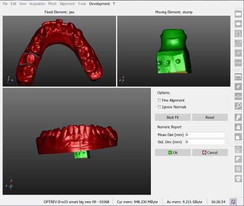
L’image ci-dessous montre l’interface de l’alignement manuel
There are 4 different areas in this screen:
- On the top left is displayed the reference object, which gives the reference position for all the project data
- On the top right is shown the moving object, that has to be moved from its current position and placed in the same reference system of all the other project data
- On the bottom are displayed both objects, so that the user can check the current position of the moving object
- On the bottom right some options and a Numeric Report are available
Procedure
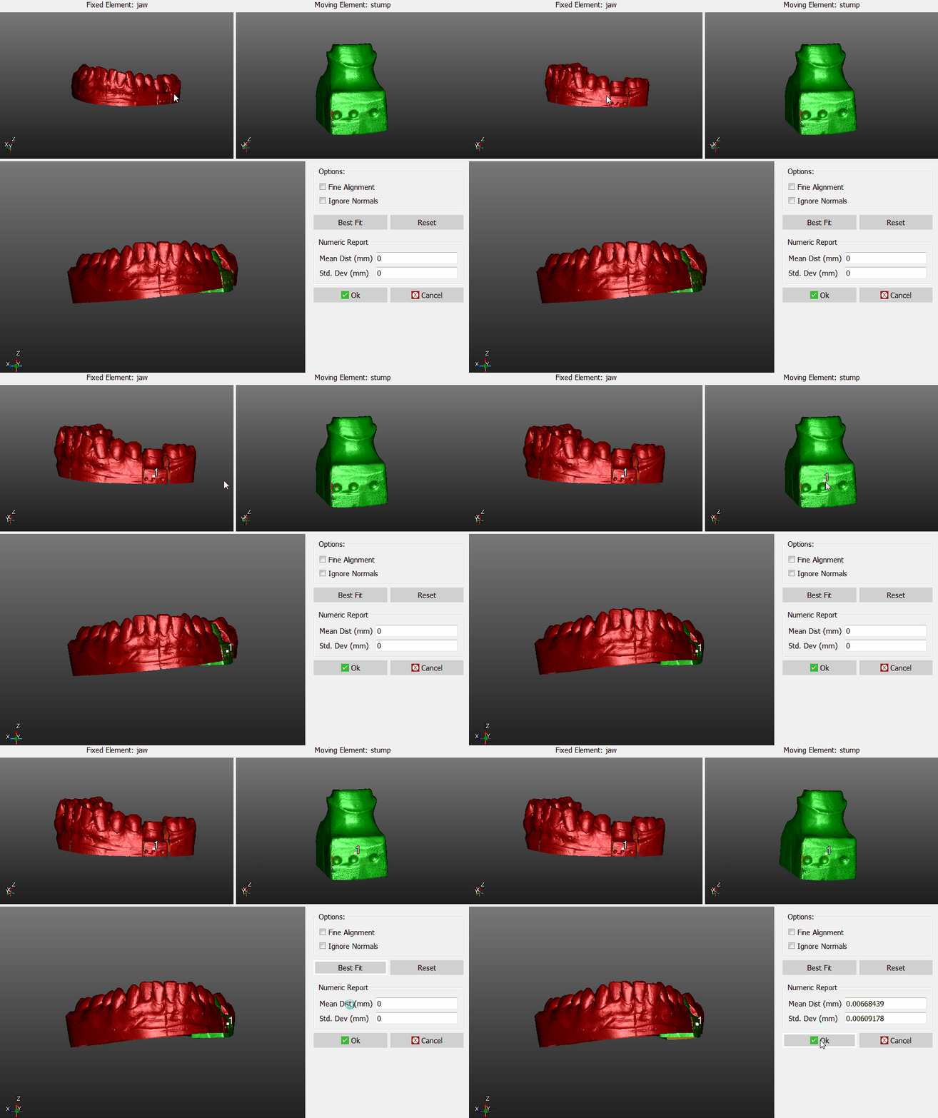
To manually align the elements:
- Place both the reference object and the moving object in the same point of view, until the parts in common are visible
- Click on the same point on both the objects
- Check in the 3D view below, if the position is more or less correct (it's not necessary, at this stage, to find the perfect position)
- Click the Best Fit button on the right
If the two objects have enough points in common, the software will find the best alignment between them. Visually check the alignment on the bottom 3D View or by reading the values in the Numeric Report.
If the alignment is correct, click Ok to confirm the new position of the moving object.
Otherwise, click the Reset button and restart the alignment.
Options
There are two options available during the manual aligment:
- Fine Alignment : usually Best Fit moves the object up to 1mm closer to the reference. If the parts in common between the two objects are really small ,use Fine Aligment to move the object not more than 0.1mm closer to the reference
- Ignore Normals : allows the user to align the internal part of an object to the external part of another, and viceversa.


