Difference between revisions of "Man Align/it"
(Created page with "==Interfaccia==") |
(Created page with "L'immagine mostra l'interfaccia dell'allineamento manuale:") |
||
| Line 27: | Line 27: | ||
==Interfaccia== | ==Interfaccia== | ||
| − | + | L'immagine mostra l'interfaccia dell'allineamento manuale: | |
{{Screenshot|Dental_2_5_manualAlignment.jpg}} | {{Screenshot|Dental_2_5_manualAlignment.jpg}} | ||
Revision as of 14:13, 20 October 2015
Contents
Allineamento
Quando vengono scansionati piç oggetti, la loro posizione reciproca non viene registrata in un primo momento. Per poter lavorare correttamente con i dati acquisiti è necessario che questi vengano registrati in uno stesso sistema di riferimento.
Prima di tutto, l'utente deve identificare quale acquisizione verrà utilizzata come riferimento per tutte le altre. Nei Progetti Strutturati, il software identifica il riferimento di ogni elemento automaticamente.
Ocgni volta che viene acquisita una nuoca informazione è necessario allineare il nuovo dato alla Acquisizione di Riferimento o ad un'altra acquisizione precedentemente allineata al resto del progetto
Ogni elemento acquisito ha una Acquisizione di Riferimento precisa. L' Albero Progetto mostra questa relazione di dipendenza: ogni elemento figlio verrà allineato al corrispettivo elemento genitore.
Allineamento Diretto
OpticalRevEng Dental può allineare le Acquisizione automaticamente:
- Selezionare nell'Albero Progetto l'elemento da allineare al resto del progetto
- Cliccare l'icona Allineamento nella Barra degli Strumenti Principale
Così facendo il software sceglierà il riferimento, analizzerà sia la scansione da allineare sia il riferimento e sposterà il primo elemento accomodandolo alla posizione del secondo.
Qualora fosse impossibile per il software stabilire una posizione di allineamento, si aprirà il passo di Allineamento Manuale.
Allineamento Manuale
L'allineamento manuale viene lanciato ogni volta che il software non riesce a portare a termine un Allineamento Diretto. È inoltre possibile accedere a questa funzionalità tenendo premuto ![]() mentre si clicca sul tasto di Allineamento nella barra degli strumenti Principale
mentre si clicca sul tasto di Allineamento nella barra degli strumenti Principale
Interfaccia
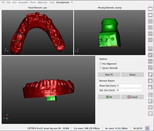
L'immagine mostra l'interfaccia dell'allineamento manuale:
There are 4 different areas in this screen:
- On the top left is displayed the reference object, which gives the reference position for all the project data
- On the top right is shown the moving object, that has to be moved from its current position and placed in the same reference system of all the other project data
- On the bottom are displayed both objects, so that the user can check the current position of the moving object
- On the bottom right some options and a Numeric Report are available
Procedure
To manually align the elements:
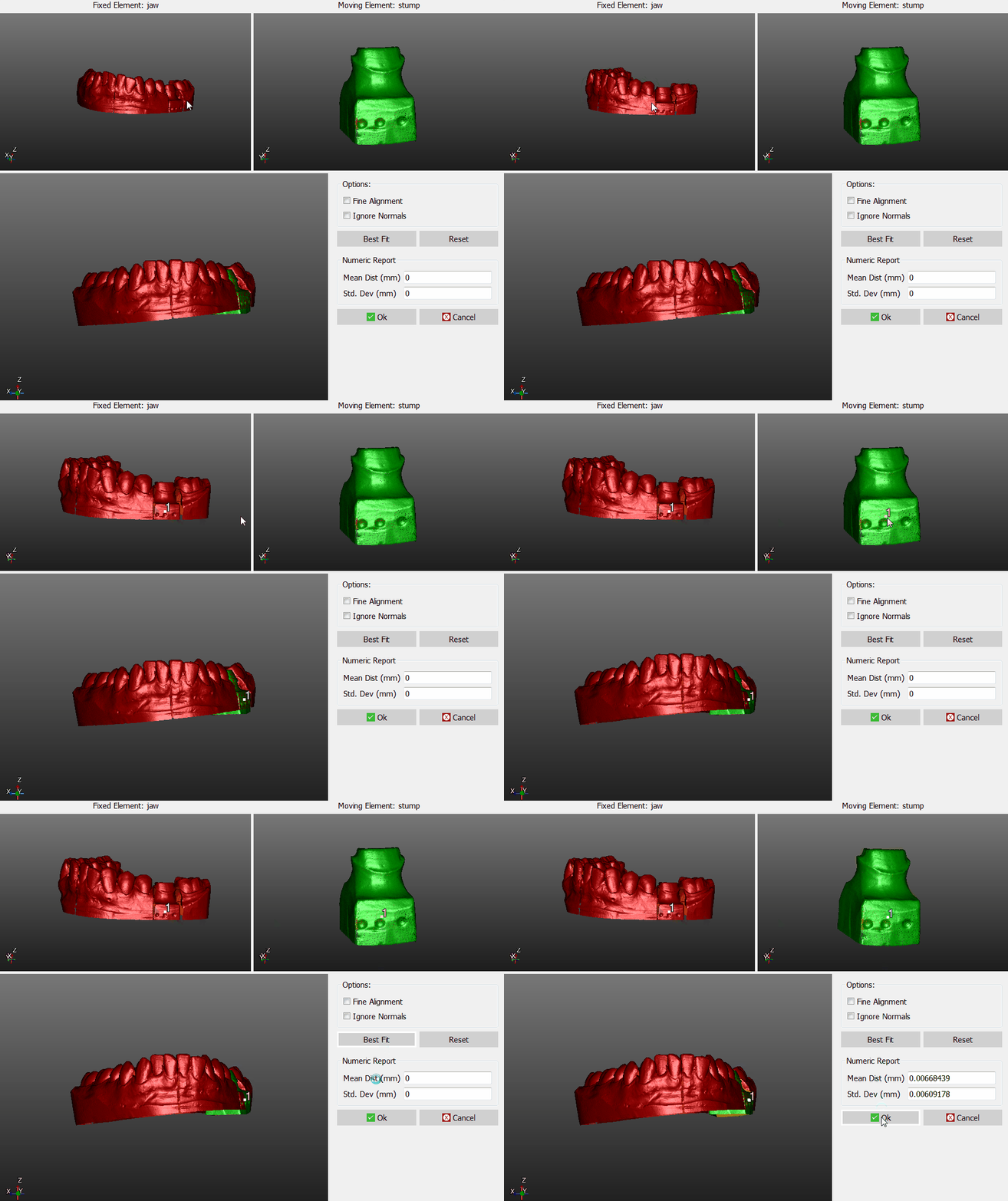
- Place both the reference object and the moving object in the same point of view, until the parts in common are visible
- Click on the same point on both the objects
- Check in the 3D view below, if the position is more or less correct (it's not necessary, at this stage, to find the perfect position)
- Click the Best Fit button on the right
If the two objects have enough points in common, the software will find the best alignment between them. Visually check the alignment on the bottom 3D View or by reading the values in the Numeric Report.
If the alignment is correct, click Ok to confirm the new position of the moving object.
Otherwise, click the Reset button and restart the alignment.
Options
There are two options available during the manual aligment:
- Fine Alignment : usually Best Fit moves the object up to 1mm closer to the reference. If the parts in common between the two objects are really small ,use Fine Aligment to move the object not more than 0.1mm closer to the reference
- Ignore Normals : allows the user to align the internal part of an object to the external part of another, and viceversa.


