Difference between revisions of "Man Align"
(Marked this version for translation) |
|||
| Line 5: | Line 5: | ||
<!--T:1--> | <!--T:1--> | ||
| − | When | + | When more than one object is acquired by the scanner, the position of each item is unrelated to the position of the others. To correctly work with the scanned data all the Acquisitions need to be located in the same reference system. |
<!--T:2--> | <!--T:2--> | ||
| − | + | First identify an Acquisition that will be used as a reference for all the others. In the '''Structured Projects''' the software automatically carries out this procedure. | |
<!--T:3--> | <!--T:3--> | ||
| − | + | Every time a new information gets acquired it is necessary to ''align'' the new data to the '''Reference Acquisition''' or to '''another acquisition already aligned at the rest of the project''' | |
<!--T:10--> | <!--T:10--> | ||
| Line 19: | Line 19: | ||
<!--T:11--> | <!--T:11--> | ||
| − | OpticalRevEng Dental can align the Acquisitions | + | OpticalRevEng Dental can align the Acquisitions by itself. Just: |
<!--T:12--> | <!--T:12--> | ||
| − | # Select from the Project Tree the element | + | # Select from the Project Tree the element to be aligned to the rest of the project |
# Click the ''Alignment Button'' in the [[Main_Toolbar|Main Toolbar]] | # Click the ''Alignment Button'' in the [[Main_Toolbar|Main Toolbar]] | ||
| Line 32: | Line 32: | ||
<!--T:15--> | <!--T:15--> | ||
| − | The manual alignment is | + | The manual alignment is launched every time the software can not complete a '''Direct Alignment''' or by holding the SHIFT key when clicking the ''Alignment Button'' in the [[Main_Toolbar|Main Toolbar]] |
== Interface == <!--T:16--> | == Interface == <!--T:16--> | ||
| Line 43: | Line 43: | ||
<!--T:19--> | <!--T:19--> | ||
| − | + | There are 4 different areas in this screen: | |
<!--T:20--> | <!--T:20--> | ||
| − | * On the '''top left''' | + | * On the '''top left''' there is the ''reference object'' that gives the reference position for all the proejct data |
| − | * On the '''top right''' | + | * On the '''top right''' there is the ''moving object'' that has to be moved from his current position to place it in the same reference system of all the other project data |
| − | * On the '''bottom''' | + | * On the '''bottom''' are visible at the same time ''both the objects'' to check the current positions of the moving object |
| − | * On the '''bottom right''' | + | * On the '''bottom right''' some options and a ''Numeric Report'' are available |
== Procedure == <!--T:21--> | == Procedure == <!--T:21--> | ||
<!--T:22--> | <!--T:22--> | ||
| − | + | To manual align: | |
<!--T:23--> | <!--T:23--> | ||
| − | # Rotate both the reference object and the moving object in | + | # Rotate both the reference object and the moving object in the same point of view to see some common part between the two objects |
# Click on the same point on both the objects | # Click on the same point on both the objects | ||
| − | # Check on the bottom 3D view | + | # Check on the bottom 3D view if the position is more or less correct (It's not necessary for them to be in a perfect position at this stage) |
# Click the '''Best Fit''' button on the right | # Click the '''Best Fit''' button on the right | ||
<!--T:24--> | <!--T:24--> | ||
| − | If the two | + | If the two objects have enough common points the software will find the best alignment between the two. Check the alignment visually on the bottom 3D View or reading the values in the Numeric Report. |
<!--T:5--> | <!--T:5--> | ||
| − | If the alignment is good | + | If the alignment is good Click '''Ok''' to confirm the new position of the ''moving object''. |
<!--T:6--> | <!--T:6--> | ||
| − | If the alignment is not good enough | + | If the alignment is not good enough Click the '''Reset''' button and start the alignment again. |
<!--T:25--> | <!--T:25--> | ||
| Line 77: | Line 77: | ||
<!--T:26--> | <!--T:26--> | ||
| − | There are two options | + | There are two options available during the manual aligment: |
<!--T:27--> | <!--T:27--> | ||
| − | # '''Fine Alignment''' : | + | # '''Fine Alignment''' : By clicking ''Best Fit'' the software will try to move the moving object up to 1mm to find a better alignment. This can create problems if the common part between the two objects is really small. With '''Fine Aligment''' enabled the software will move the moving object not more than 0.1mm |
| − | # '''Ignore Normals''' : The objects have an inside and an outside. When the software | + | # '''Ignore Normals''' : The objects have an inside and an outside. When the software searches for an alignment it refuses to align the inside of one object with the outouside of the other. To ignore the differences between inside and outside Check the '''Ingore Normals''' option |
=Next= <!--T:8--> | =Next= <!--T:8--> | ||
Revision as of 12:30, 29 July 2015
Contents
Alignment
When more than one object is acquired by the scanner, the position of each item is unrelated to the position of the others. To correctly work with the scanned data all the Acquisitions need to be located in the same reference system.
First identify an Acquisition that will be used as a reference for all the others. In the Structured Projects the software automatically carries out this procedure.
Every time a new information gets acquired it is necessary to align the new data to the Reference Acquisition or to another acquisition already aligned at the rest of the project
Every acquired information will have a specific Reference Acquisition. The Project Tree will show this relation, every child will be aligned to his parent node in the tree.
Direct Alignment
OpticalRevEng Dental can align the Acquisitions by itself. Just:
- Select from the Project Tree the element to be aligned to the rest of the project
- Click the Alignment Button in the Main Toolbar
The software will select the most appropriate reference item, analyze the selcted acquisition and the reference item, and try to identify the correct position of the selected item inside the reference item.
If no alignment can be identified by the software then a Manual Alignment will start.
Manual Alignment
The manual alignment is launched every time the software can not complete a Direct Alignment or by holding the SHIFT key when clicking the Alignment Button in the Main Toolbar
Interface
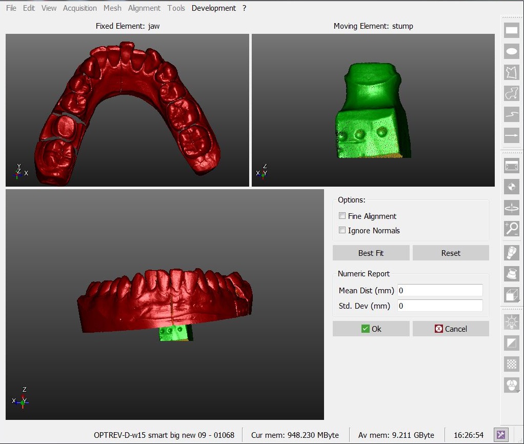
During the manual alignment the interface will change.
There are 4 different areas in this screen:
- On the top left there is the reference object that gives the reference position for all the proejct data
- On the top right there is the moving object that has to be moved from his current position to place it in the same reference system of all the other project data
- On the bottom are visible at the same time both the objects to check the current positions of the moving object
- On the bottom right some options and a Numeric Report are available
Procedure
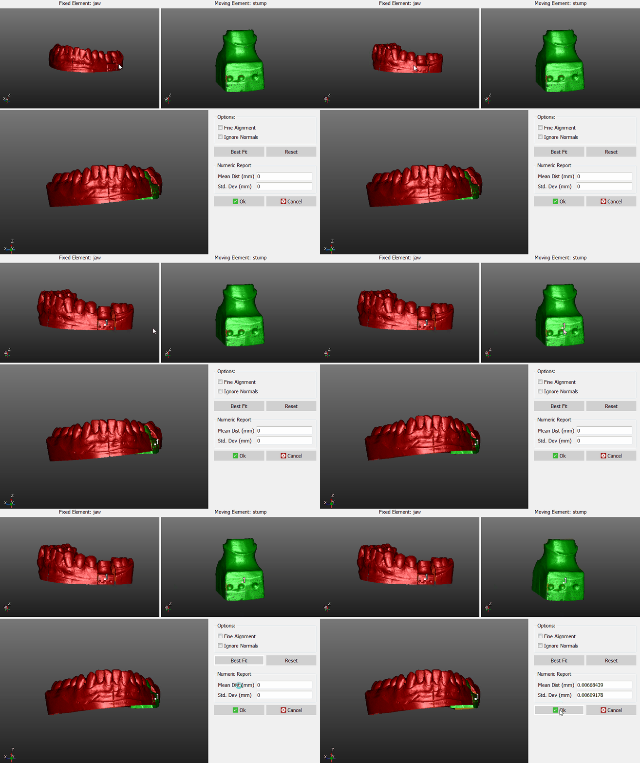
To manual align:
- Rotate both the reference object and the moving object in the same point of view to see some common part between the two objects
- Click on the same point on both the objects
- Check on the bottom 3D view if the position is more or less correct (It's not necessary for them to be in a perfect position at this stage)
- Click the Best Fit button on the right
If the two objects have enough common points the software will find the best alignment between the two. Check the alignment visually on the bottom 3D View or reading the values in the Numeric Report.
If the alignment is good Click Ok to confirm the new position of the moving object.
If the alignment is not good enough Click the Reset button and start the alignment again.
Options
There are two options available during the manual aligment:
- Fine Alignment : By clicking Best Fit the software will try to move the moving object up to 1mm to find a better alignment. This can create problems if the common part between the two objects is really small. With Fine Aligment enabled the software will move the moving object not more than 0.1mm
- Ignore Normals : The objects have an inside and an outside. When the software searches for an alignment it refuses to align the inside of one object with the outouside of the other. To ignore the differences between inside and outside Check the Ingore Normals option
Next
Now that you know how to align an object to the rest of the project you can return to the Main Page or continue to the Mesh Generation page

