Difference between revisions of "Interaction"
| Line 5: | Line 5: | ||
<!--T:10--> | <!--T:10--> | ||
| − | Here | + | Here-below an example of 3D interaction on a selected Mesh in OpticalRevEngDental. |
<!--T:11--> | <!--T:11--> | ||
| Line 11: | Line 11: | ||
<!--T:12--> | <!--T:12--> | ||
| − | It is possible to interact with the | + | It is possible to interact with the 3D View using the mouse and the keyboard, the context menu, the view menu and the view toolbar. |
=== Mouse Interaction === <!--T:13--> | === Mouse Interaction === <!--T:13--> | ||
| Line 19: | Line 19: | ||
<!--T:2--> | <!--T:2--> | ||
| − | Here | + | Here-below a list of the provided mouse/keyboard combinations: |
<!--T:15--> | <!--T:15--> | ||
Revision as of 10:41, 31 August 2015
Contents
Main View
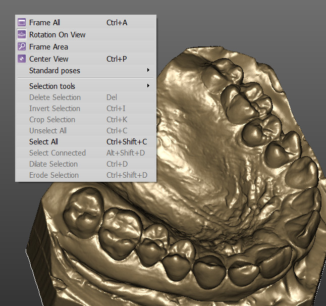
Here-below an example of 3D interaction on a selected Mesh in OpticalRevEngDental.
It is possible to interact with the 3D View using the mouse and the keyboard, the context menu, the view menu and the view toolbar.
Mouse Interaction
The user can interact with the orientation of the 3d object through either the use of the mouse or more specific tools that can be selected in the View menu, the View toolbar or the Context menu.
Here-below a list of the provided mouse/keyboard combinations:
-
 +
+  or
or  +
+  : Pan the camera in 2D
 -
 : Rotate the camera freely around the 3D Object
 -
 +
+  : Rotate the camera restricted to Y axis of the 3D View
 -
 +
+  : Rotate the camera restricted to X axis of the 3D View
 -
 +
+  : Rotate the camera restricted to Z axis of the 3D View
 -
 : Change the Zoom
 -
 : Accesses the context menu
 -
 + [[File::Mouse_right.png|x25px|inline]]: Change the position of the light source in the 3D View
 -
 : Use the current tool (E.g. Rectangular Selection, Hole Filling, ...)
 -
 +
+  : Invert the current tool if available (E.g. Deselect points instead of Select points, ...)
 -
 + Number from 1 to 7 : Change the 3D View in one of the default positions (E.g. Frontal, Back, Top, ...)
In the software options it is possible to enable an "Alternative Interaction" mode where the middle mouse button and the right mouse button are swapped to give an interaction more similar to other CAD softwares.
Context Menu and View Menu
The view menu and the 3D View context menu contain some tools that can be used to interact with the 3D View.
- Frame All (
 + A) : The 3D camera will move to show on screen all the current selected 3D Objects
 - Rotation On View : If this option is enabled the rotation will ignore the current selected 3D Objects, if is disabled the center of the rotation will be the baricenter of the selected 3D Objects
- Area Frame Tool: This tool allows to draw with inline a rectangle. The rectangle will become the new camera view.
- Center View (
 + P) : The currently selected 3D Objects are moved at the center of the screen without changing the Zoom
 - Standard Poses : Sub menu to apply default 3D views:
The context menu contains other tools described in the Data Editing page.
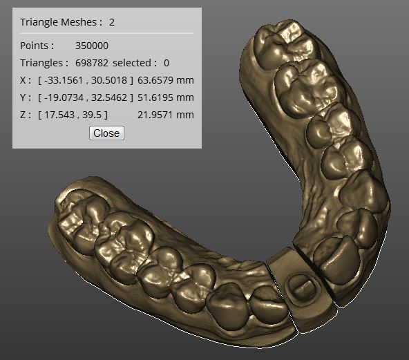
Data Information Window
In the view menu it is possible to enable the Data Information Window with the View Data Window (![]() +
+ ![]() + I) action.
+ I) action.
This windows gives some information about the current selected 3D Objects.
- Description: a line that describes the type of currently selected objects (E.g. Triangle Mesh: 2, Range Images: 6, ...)
- Points: the number of points of the currently selected objects
- Faces: the number of faces, available only for the triangular meshes
- Selected: the number of selected point/faces of the current selected object
- Size and Position: the minimum, maximum coordinates of the volume of the current selected objects, and their size in every direction
Now you can return to the Main Page or continue to the Project Tree page

