Dental Interactor Options
Interactor
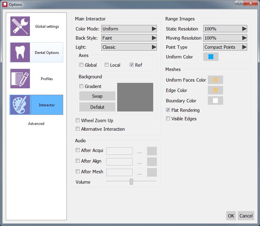
This Options Page provides all the settings about the 3D visualization of the Acquired data and the interaction with the user.
Main Interactor
The main interactor section has the following properties:
- Color Mode : What color the 3D objects will have in the 3D View. There are 3 choiches:
- Uniform : The software will use the color specified in the Uniform Color settings of this page for the specific object type visualized
- Unique : The software will use a specific randomized color for every object
- Texture : The software will use the color acquired directly by the scanner if available
- Axes : Here is possible to enable the visualization of the spacial axes (X, Y, Z) in three different positions.
- A Background Section with:
- Gradient : If enabled the 3D view backround will be a gradient between two colors. If disabled it will be a solid color
- Swap : It swaps the top and bottom color of the backgound when gradient is enabled
- Default : Recovers the default bacground's setting
- The background preview :
- A double-click on the top of the background preview modifies the background top color
- A double-click on the bottom of the background preview modifies the background bottom color
- Wheel Zoom Up : If enabled inverts the zoom function with the mouse spin
- Alternative Interaction : Swaps the middle and the right mouse button for the Mouse Interaction
Audio
This section allows to select an mp3 file that the software will play after every main function of the software (Acquisition, Alignment, Mesh Generation)
Range Images
This section provide settings specific for the 3D visualization of the Range Images acquired by the scanner
- Static Resolution : The percentage of points from the original data that the software will show when nothing is moving in the 3D View. Can be lowered on low power systems to speed-up the 3D Visualization
- Moving Resolution : The percentage of points from the original data that the software will show when the 3D View is moving. Can be lowered on low power systems to speed-up the 3D Visualization
- Point Type : How any single point of the Range Images is visualized:
- Compact Points : The points will become bigger as the 3D Visualization is zoomed.
- Points : The points will always be small
- Uniform Color : The color the software will use to for the 3D Visualization of Range Images if the Color Mode is Uniform
Meshes
This section provides settings specific to the 3D visualization of Meshes
- Uniform Face Color : The color the software will use to for the 3D Visualization of Meshes if the Color Mode is Uniform
- Edge Color : The color used by the software to identify the margin of every mesh triangle if the Visible Edges options is enabled
- Boundary Color : The color used by the software to highlight the borders of the Meshes
- Flat Rendering : Draw every single triangle of the meshes alone to better see the mesh structure
- Visible Edges : Draw the sides of every tringle in the meshes to better see the mesh structure
