Difference between revisions of "Accessories"
| (17 intermediate revisions by 3 users not shown) | |||
| Line 1: | Line 1: | ||
| − | + | {{Language bar}} | |
| − | {{DISPLAYTITLE:Accessories}} | + | {{DISPLAYTITLE:Accessories|noerror}} |
<translate> | <translate> | ||
=Accessories= <!--T:2--> | =Accessories= <!--T:2--> | ||
| Line 10: | Line 10: | ||
<!--T:5--> | <!--T:5--> | ||
| − | The Basic Kit comes with every scanner, inside a case | + | The Basic Kit comes with every scanner, inside a case, containing the model holder, the multi-die holder and the calibration kit. |
===Model Holder=== <!--T:6--> | ===Model Holder=== <!--T:6--> | ||
<!--T:7--> | <!--T:7--> | ||
| − | The Model Holder is the main support | + | The Model Holder is the main support on which it's possible to place jaws or other objects inside the scanner. If mounted on this support, the objects are guaranteed to be in the best possible position for the scanner acquisition. |
<!--T:8--> | <!--T:8--> | ||
| Line 21: | Line 21: | ||
<!--T:9--> | <!--T:9--> | ||
| − | [[File:Model_holder_big.png]] | + | [[File:Model_holder_big.png|300px]] |
| − | [[File:Model_holder_small.png]] | + | [[File:Model_holder_small.png|300px]] |
===Multi-Die Support=== <!--T:10--> | ===Multi-Die Support=== <!--T:10--> | ||
| Line 30: | Line 30: | ||
<!--T:12--> | <!--T:12--> | ||
| − | ;It's important to keep the | + | ;It's important to keep the Multi-Die clean and black to reduce the possible interferences between the Multi-Die and the object during the acquisition phase. |
<!--T:13--> | <!--T:13--> | ||
| − | [[File:Model_multidie_big.png]] | + | [[File:Model_multidie_big.png|300px]] |
| − | [[File:Model_multidie_small.png]] | + | [[File:Model_multidie_small.png|300px]] |
===Calibration Kit=== <!--T:14--> | ===Calibration Kit=== <!--T:14--> | ||
<!--T:15--> | <!--T:15--> | ||
| − | The Calibration Kit is a planar surface with a pattern of circles placed on a bended support.<br/> | + | The Calibration Kit is a planar surface with a pattern of circles, placed on a bended support.<br/> |
Every calibration kit is measured and analized with high-precision machines.<br/> | Every calibration kit is measured and analized with high-precision machines.<br/> | ||
The measurement is then saved on a xml file and every kit has it's own xml description file. <br/> | The measurement is then saved on a xml file and every kit has it's own xml description file. <br/> | ||
| Line 45: | Line 45: | ||
<!--T:16--> | <!--T:16--> | ||
| − | ;It's really important to handle the kit with care and to avoid touching the planar surface. Every modification of the planar surface like scratches | + | ;It's really important to handle the kit with care and to avoid touching the planar surface. Every modification of the planar surface, like scratches or dirt, can make the calibration system unreliable. |
<!--T:17--> | <!--T:17--> | ||
| − | [[File:Calibration_kit.jpg]] | + | [[File:Calibration_kit.jpg|300px]] |
==Dynamic Articulation Module== <!--T:18--> | ==Dynamic Articulation Module== <!--T:18--> | ||
<!--T:19--> | <!--T:19--> | ||
| − | + | In order to use the dynamic articulation module, some special supports are needed: a specific '''Axis Calibration Object''' and a special '''Mounting Plate''' for every supported articulator. | |
===Mounting Plates=== <!--T:20--> | ===Mounting Plates=== <!--T:20--> | ||
<!--T:21--> | <!--T:21--> | ||
| − | + | Up to the present, our dynamic articulation module supports 4 different mounting plates. | |
<!--T:22--> | <!--T:22--> | ||
| − | * Artex : [[File:Basetta_artex.jpg|300px | + | * Artex : [[File:Basetta_artex.jpg|300px]] |
| − | * Kavo : [[File:Basetta_cavo.jpg|300px | + | * Kavo : [[File:Basetta_cavo.jpg|300px]] |
| − | * Adesso : [[File:Basetta_adesso.jpg|300px | + | * Adesso : [[File:Basetta_adesso.jpg|300px]] |
| − | * Sam : [[File:Basetta_sam.jpg|300px| | + | * Sam : [[File:Basetta_sam.jpg|300px]] |
| + | * Bioart : [[File:Basetta_bioart.jpg|300px]] | ||
| + | * Denar : [[File:Basetta_denar.jpg|300px]] | ||
| + | |||
| + | |||
| − | ===Axis | + | ===Axis Calibration Object=== <!--T:23--> |
<!--T:24--> | <!--T:24--> | ||
| − | This is a specific object | + | This is a specific object, which fits on every mounting plate, used to calibrate the movement system for the Dynamic Articulation Module. |
<!--T:25--> | <!--T:25--> | ||
| − | ;It's important to keep the object clean and handle it with care. Every modification of the object surface like scratches | + | ;It's important to keep the object clean and handle it with care. Every modification of the object surface, like scratches or dirt, can make the calibration system unreliable. |
<!--T:26--> | <!--T:26--> | ||
| − | [[File:Kavo_oggettotest.jpg| | + | [[File:Kavo_oggettotest.jpg|300px|]] |
| + | |||
| + | ===Concept Quad Support=== <!--T:27--> | ||
| + | |||
| + | <!--T:28--> | ||
| + | The Concept Quad Support is provided together with the additional Concept Quad Scanning Module and it allows to place two antagonist quadrant models and their stumps in the scanner to be scanned in together at the same time. | ||
| + | |||
| + | <!--T:29--> | ||
| + | ;It's important to keep the model holder clean and black to reduce the possible interferences between the model holder and the object during the acquisition phase. | ||
| + | |||
| + | <!--T:30--> | ||
| + | [[File:Concept_holder_big.png|300px]] | ||
| + | [[File:Concept_holder_small.png|300px]] | ||
| + | |||
| + | ==Reference Rim== <!--T:38--> | ||
| + | |||
| + | <!--T:39--> | ||
| + | The Reference Rim offers reference points to grant accurate dimensional results during the scanning process. Although dimensional accuracy is granted for the vast majority of all objects, in case of scanning small metalic objects, such as metal abutments, or other difficult materials, the Reference Rim offers even better results and safety. | ||
| + | |||
| + | '''NOTE THAT THE REFERENCE RIM IS A PRECISION OBJECT! OCCLUSAL AND WHITENING SPRAYS, AND CLEANING SOLVENTS, DAMAGE ITS SURFACE!''' | ||
| + | '''DO NOT SPRAY ANY SUBSTANCE ON THE RIM AS TO DO SO IT WILL NO LONGER BE USABLE FOR SCANNING NOR FOR CALIBRATING!''' | ||
| + | |||
| + | |||
| + | |||
| + | <!--T:40--> | ||
| + | [[File:Reference rim.png|300px]] | ||
| + | |||
| + | =Accessories not provided by Open Technologies= <!--T:33--> | ||
| + | |||
| + | ==TouchScreen Monitor== <!--T:34--> | ||
| + | |||
| + | <!--T:35--> | ||
| + | Starting version 4.5 OpticalRevEng Dental can be also used with any kind of touchscreen monitor. | ||
| + | |||
| + | ==3D Mouse== <!--T:36--> | ||
| + | |||
| + | <!--T:37--> | ||
| + | Starting version 4.5 OpticalRevEng Dental can be also controlled with any kind of 3D Mouse. | ||
| + | |||
| + | |||
</translate> | </translate> | ||
Latest revision as of 10:32, 28 May 2018
Accessories
The Open Technologies' Scanners come with a fixed set of basic accessories and some extra accessories that depend on the specific scanner model.
Base Kit
The Basic Kit comes with every scanner, inside a case, containing the model holder, the multi-die holder and the calibration kit.
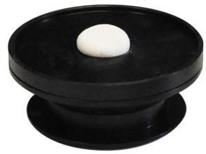
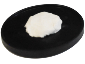
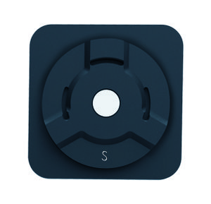
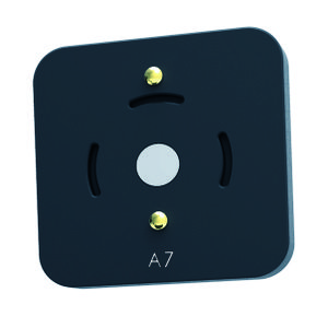
Model Holder
The Model Holder is the main support on which it's possible to place jaws or other objects inside the scanner. If mounted on this support, the objects are guaranteed to be in the best possible position for the scanner acquisition.
- It's important to keep the model holder clean and black to reduce the possible interferences between the model holder and the object during the acquisition phase.
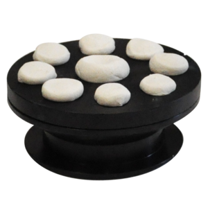
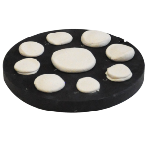
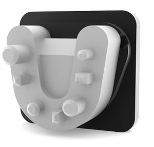
Multi-Die Support
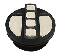
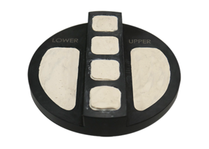
The Multi-Die support is used to acquire multiple stumps with a single acquisition. The position are later automatically identified by the software.
- It's important to keep the Multi-Die clean and black to reduce the possible interferences between the Multi-Die and the object during the acquisition phase.
Calibration Kit
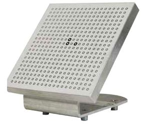
The Calibration Kit is a planar surface with a pattern of circles, placed on a bended support.
Every calibration kit is measured and analized with high-precision machines.
The measurement is then saved on a xml file and every kit has it's own xml description file.
The kit is used to recalibrate the optical head of the scanner.
- It's really important to handle the kit with care and to avoid touching the planar surface. Every modification of the planar surface, like scratches or dirt, can make the calibration system unreliable.
Dynamic Articulation Module
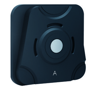
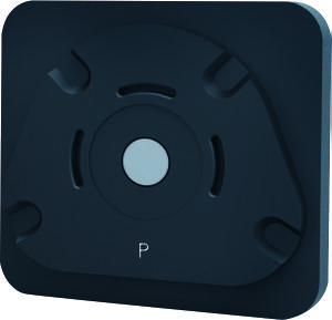
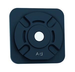
In order to use the dynamic articulation module, some special supports are needed: a specific Axis Calibration Object and a special Mounting Plate for every supported articulator.
Mounting Plates
Up to the present, our dynamic articulation module supports 4 different mounting plates.
Axis Calibration Object
This is a specific object, which fits on every mounting plate, used to calibrate the movement system for the Dynamic Articulation Module.
- It's important to keep the object clean and handle it with care. Every modification of the object surface, like scratches or dirt, can make the calibration system unreliable.
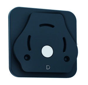
Concept Quad Support
The Concept Quad Support is provided together with the additional Concept Quad Scanning Module and it allows to place two antagonist quadrant models and their stumps in the scanner to be scanned in together at the same time.
- It's important to keep the model holder clean and black to reduce the possible interferences between the model holder and the object during the acquisition phase.
Reference Rim
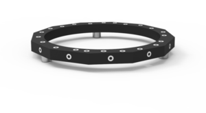
The Reference Rim offers reference points to grant accurate dimensional results during the scanning process. Although dimensional accuracy is granted for the vast majority of all objects, in case of scanning small metalic objects, such as metal abutments, or other difficult materials, the Reference Rim offers even better results and safety.
NOTE THAT THE REFERENCE RIM IS A PRECISION OBJECT! OCCLUSAL AND WHITENING SPRAYS, AND CLEANING SOLVENTS, DAMAGE ITS SURFACE!
DO NOT SPRAY ANY SUBSTANCE ON THE RIM AS TO DO SO IT WILL NO LONGER BE USABLE FOR SCANNING NOR FOR CALIBRATING!
Accessories not provided by Open Technologies
TouchScreen Monitor
Starting version 4.5 OpticalRevEng Dental can be also used with any kind of touchscreen monitor.
3D Mouse
Starting version 4.5 OpticalRevEng Dental can be also controlled with any kind of 3D Mouse.
